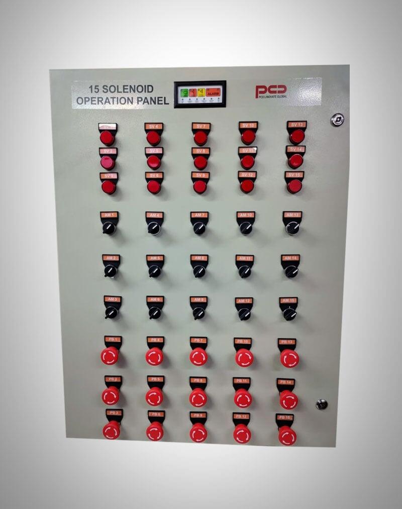
Push Button Panel:
- 15 Auto/Manual mode selector switches with led Indication.
- 15 Push Buttons (on panel) for manual operation of Solenoid Valve.
- 15 Indication (Industrial Lamp) for respective Solenoid Valve Operation.
- 15 RTD digital input (NO/NC Contact) facility.
- 15 Input (NO/NC Contact) circuit for field push station.
- 15 Solenoid Valve driver circuit.
- 1 Hooter : 24V/500mA
- 1 NO/NC Contact: common indication of Solenoid Valve Operation.
- 1 Additional 24V output circuit.
- Additional Led Indication on panel
- System ON
- Common Fault
- Supply Fault
- Hooter Fault
- Lamp test
- Reset
- Alarm
- Silence
- Additional keys on panel
- Panel reset
- Alarm
- Silence
- Lamp Test
Panel Working
Downloads
Panel Working
RTD digital input:
- Potential Free Contact (NO): Input to Panel.
- On receiving NO, panel will not perform any action.
- On receiving NC, panel will perform as follows
- Respective Solenoid circuit will be ON: 24V/500mA.
- Respective Lamp Indication will be ON.
- Common Hooter will be ON : 24V/500mA.
- Local Alarm will be ON.
- Common Alarm Relay will be ON: Provides NC potential free contact.
- Panel will response to this RTD digital input only when respective auto/manual selector switch is positioned to auto mode.
Manual Push Button (On Panel):
- 15 Respective Push Button on panel.
- When button is not pressed then panel will not perform any action.
- When respective button is pressed then panel will perform as follows
- Respective Solenoid circuit will be ON: 24V/500mA.
- Respective Lamp Indication will be ON.
- Common Hooter will be ON : 24V/500mA.
- Local Alarm will be ON.
- Common Alarm Relay will be ON: Provides NC potential free contact.
- Panel will response to this manual push button only when respective auto/manual selector switch is positioned to manual mode.
Field Push Button (Remote):
- 15 Respective Push Button on remote.
- When button is not pressed then panel will not perform any action.
- When respective button is pressed then panel will perform as follows
- Respective Solenoid circuit will be ON: 24V/500mA.
- Respective Lamp Indication will be ON.
- Common Hooter will be ON : 24V/500mA.
- Local Alarm will be ON.
- Common Alarm Relay will be ON: Provides NC potential free contact.
- Panel will response to this field push button only when respective auto/manual selector switch is positioned to manual mode.
Additional key on Panel:
1. Reset
| Key Pressed | Panel will perform reset. |
| Key Not Pressed | Panel will not perform reset. |
2. Alarm
| Key Pressed | Hooter and local alarm will be ON |
| Key not pressed | Hooter and local alarm will be OFF |
3. Silence
| Key Pressed | Hooter and local alarm will be OFF |
| Key Not Pressed | Panel in working condition. |
4. Lamp Test
| Key Pressed | All indication on panel will be ON. |
| Key Not Pressed | Panel in working condition. |
Additional Led Indication on Panel
1. System On Led.
- Indicates panel working status.
| Led ON | Panel power is ON. |
| Led OFF | Panel power is OFF. |
2. Common Fault
- Indicates Panel fault status.
| Led ON | Panel detected any fault. |
| Led OFF | Panel has not detected any fault. |
3. Supply Fault
- Indicates panel power fault status.
| Led ON | Panel main power is OFF. |
| Led OFF | Panel main power is ON. |
4. Hooter Fault
- Indicates panel hooter wiring status.
| Led ON | Panel detected hooter fault, hooter wiring open or short. |
| Led OFF | Panel has not detected any hooter fault. |
5. Common Fault
- Indicates Panel fault status.
| Led ON | Panel detected any fault. |
| Led OFF | Panel detected any fault. |
6. Reset
- Indicates panel reset status.
| Led ON | Panel is getting reset. |
| Led OFF | Panel in working condition. |
7. Alarm
- Indicates hooter audible status.
| Led ON | Alarm key on panel is pressed. |
| Led OFF | Alarm key on panel is not pressed. |
8. Silence
- Indicates hooter silence status.
| Led ON | Silence key on panel is pressed. |
| Led OFF | Silence key on panel is not pressed. |
9. Lamp Test
- Indicates lamp test key status.
| Led ON | Lamp test key on panel is pressed. |
| Led OFF | Lamp test key on panel is not pressed. |
Downloads
Our Clients