Alarm Point Locator
Model No.: LHS-APL
Introduction:
LHS Alarm Point Locator is a microprocessor based product. The LHS cable is a pair of steel wire with conductive plating insulated by a thermo sensitive material. The pair of wires are twisted and enclosed in a protective outer shield to form a cable. This wire is used to sense Heat. In case temperatures rise anywhere along the length of cable the thermo sensitive material will breakdown and melt. The two steel wires will then make contact at that point. Because the steel wire used has a specific resistance, the resistance from the panel to the alarm point is linearly proportional to the cable length.
There are various makes LHS cable. The basic difference between these Cables is their resistance per Kilo meter.
1) Kidde: 100 ohms per Kilometer.
2) Protector Wire: 150 ohms per Kilometer.
3) Thermo Cable: 168 ohms per Kilometer.
4) System Sensor:
Construction:
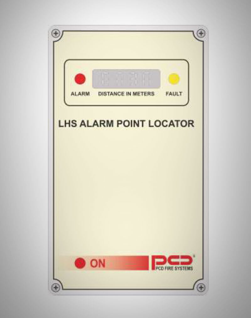
This Module is built in an IP56 ABS enclosure. The front fascia of the panel has LED indications for Alarm on the LHS cable and Fault on the cable between the Module and the LHS Cable.
A power ON LED will glow when the power supply is available. The Panel has a numeric display for distance indications which consist of 4 nos. x 7 segments.
Special Features
Downloads
Special Features
Features of LHS Wire:
- Twin-conductor switching heat sensing cable.
- Effective monitoring at precise point of risk.
- Economical, reliable and durable detection.
- Simple and easy to install.
- Applied where other types of fire detection are unsuitable.
- Operating temperature is -65 to +200 Degrees C.
Use of LHS Cable:
- Rack storage.
- Vehicle engine bays.
- Turbines.
- Ships' holds.
- Rail locomotives and rolling Stock.
Dimensions:
- Width: 75mm, Height: 200mm, Depth: 120mm
Calibration:
There are 2 Potentiometers in the LHS unit. Vr1 (Min) & (MAX). VR1 is Used to set the start point and Vr2 set the max steps.
Set up is done in simple steps.
1) Start Point: Short the alarm sensing cable at its starting point from where the LHS cable is terminated. Now adjust Vr1 to indicate Zero on the distance indicator.
2) End Point: If the cable length used is known then short the end point of the LHS Cable and observe the distance readout. If the distance is wrong then correct it by adjusting Vr2 to indicate the correct distance on the distance indicator.
Repeat 1) & 2) at least 2 to 3 times to ensure best calibration.
Fault detection:
An EOL box is provided which is placed at the END of the LHS cable. the EOL is fitted with a 3rd Potentiometer.
3) Incase the display shows Open you need to Adjust this Potentiometer so that the LHS unit indicates Normal. To test if Open circuit detection is working disconnect the end interwire of the LHS cable and observe that the fault indication comes ON.
Normal Condition:
with no short or open circuit fault will stay blank.
Theory of Operation:
The equipment is design to perform the basic functions of an ohmmeter. However the display shall be calibrated to read out in meters. In addition the End of Line resistor shall be monitored by the equipment so that in case there is a break in the cable the panel indicates an open circuit fault.
The Facility is also provided to pre-load a compensation value for the cable resistance between the panel and the start of the LHS cable terminator.
Electrical:
- Supply: 24v DC.
- Alarm Relay: Isolated CO contacts.
- Fault Relay: Isolated CO contacts.
- Fire / Fault: 2 wire output to Conv FAP.
- 4700 Ohms = normal
- 470 Ohms = alarm
- Open circuit is = fault.
Indications:
- LED's: System ON, Alarm and Fault.
- Location Indicator: 7 segment 4 digits.
- EOL Resistor: 500 OHMS Potentiometer
Downloads
Our Clients