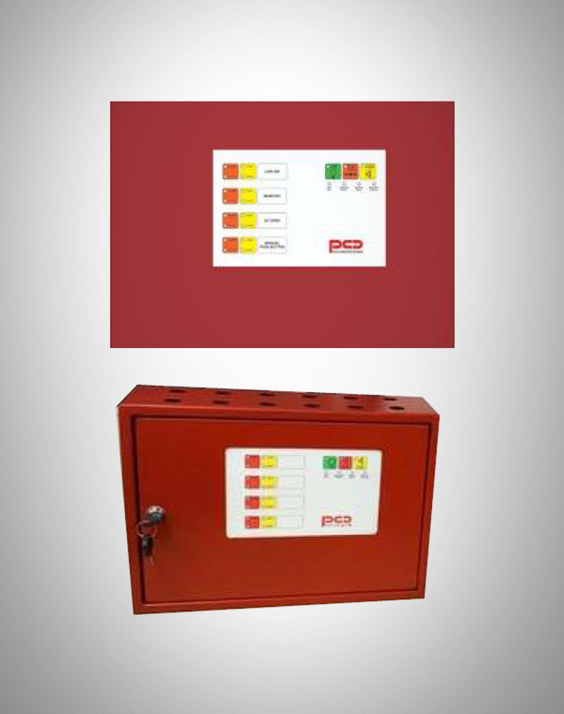
DV Panel Standard:
(Standard Deluge Value Panel)
Model: 20-DVP-02
Special Features
Single Line Diagram
Operation
Specification
Field Wiring and Termination
Downloads
Special Features
Operation Features:
This DV panel will be the electrical interface between the DV and the Site Fire alarm system. The Panel shall monitor itself and all connected input circuits including the supply for fault and shall signal the FAS system accordingly.
In case the Deluge valve Opens (Automatically or Manually) this will cause the pressure switch mounted on the outlet to sense the change in pressure and change state. This in turn will switch on the DV open indication. Along with this panel will switch on its external alarm signal to annunciate the alarm condition on the main FAP or repeater panel.
Manual Operation:
A push button on the DV panel will enable the operator to open the DV manually. When this button is operated the "Manual" indication will come on and the Solenoid mounted on the DV will be switched on. The Audio Visual alarm will also sound.
Remote Operation:
As above in case the DV need's to be opened remotely, A push button or relay contact can be used to signal the "MAIN FAP" indication along with this the Solenoid mounted on the DV will be switched on. The Audio Visual alarm will also sound.
Silence:
The Audio Alarm can be silenced by operating the silence button on the DV panel. When the Air Pressure is restored and the DV closes the Panel will automatically revert to its standby state.
Fault Monitoring:
Fault Monitoring: All wires connected to inputs shall be monitored for Cable open, Short and earth fault. The battery shall be monitored for low or disconnected status if installed. In case of complete failure also the NC Fault contact shall change to NO to indicate to the Main FAP or repeater panel a fault.
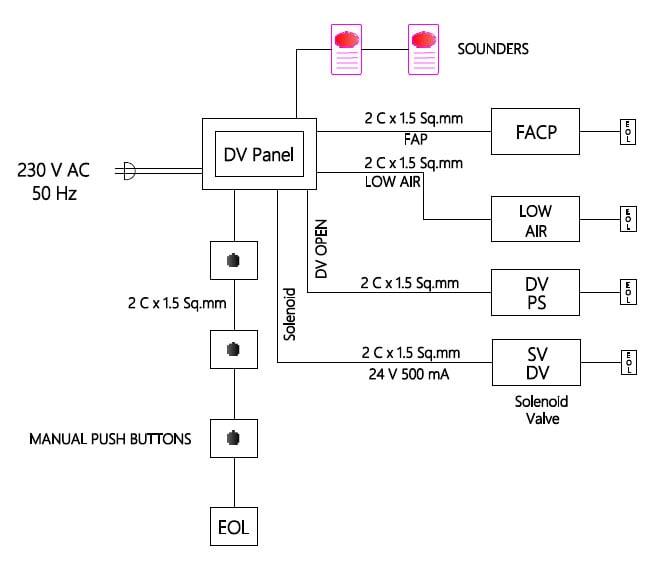
Single Line Diagram
- There are 4 inputs to panel.
- Low Air(Supervised).
- DV Open (Supervised).
- Main FAP (Supervised).
- Manual Push Button(Supervised).
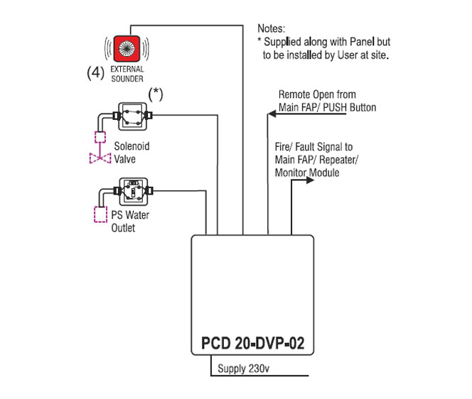
- 1 Solenoid Output : 24VDC / 500mA (Supervised).
- 4 External Sounder Circuits(NOT Supervised).
- 1 Alarm Relay Potential free Contact Output.
- 1 Fault Relay Potential free Contact Output.
- 1 Local Alarm (Buzzer).
- Led Indications (Inputs activation status) on Panel.
- Led Indications (Inputs cable fault) on Panel.
- Led Indications for Power and Battery.
- Led Indication for Solenoid cable fault.
- 1 push button for silence operation(Panel).
- 1 push button for lamp test (Panel).
- 1 push button for manual push button (Panel).
Operation
1. LOW AIR
- Potential Free Contact (NO): Input to Panel.
- Cable Open & Short fault indication for this input is provided.
- On receiving NO panel will not perform any action.
- On receiving NC panel will perform as follows
- Low Air alarm led will be ON.
- 1st external Sounder will be ON: 24V/500mA.
- Local alarm(Buzzer) will be ON.
- Common Fault Relay will be ON: Provides NC potential free contact.
- Silence push button is pressed then External Sounder will be OFF and local alarm will be OFF.
2. DV OPEN
- Potential Free Contact(NO): Input to Panel.
- Cable Open & short fault indication for this input is provided.
- On receiving NO panel will not perform any action.
- On receiving NC panel will perform as follows
- DV Open alarm led will be ON.
- 2nd external Sounder will be ON:24V/500mA.
- Local alarm (Buzzer) will be ON.
- Common alarm Relay will be ON: Provides NC potential free contact.
- Silence push button is pressed then External Sounder will be OFF and local alarm will be OFF.
3. Main FAP
- Potential Free Contact(NO): Input to Panel.
- Cable Open & Short fault indication for this input is provided.
- On receiving NO panel will not perform any action.
- On receiving NC panel will perform as follows
- MAIN FAP alarm led will be ON.
- 3rd external sounder will be ON: 24V/500mA.
- Solenoid will be ON: 24V/500mA.
- Local alarm (Buzzer) will be ON.
- Common alarm Relay will be ON: Provides NC potential free contact.
- Silence push button is pressed then External Sounder will be OFF and local alarm will be OFF.
4. Manual Push Button (Panel)
- Push Button on Panel.
- When Button is not pressed then panel will not perform any action.
- When Button is pressed then panel will perform as follows
- Manual Push Button alarm led will be ON.
- 4th external Sounder will be ON: 24V/500mA.
- Solenoid will be ON: 24V/500mA.
- Local alarm (Buzzer) will be ON.
- Common Alarm Relay will be ON: Provides NC potential free contact.
- Silence push button is pressed then External Sounder will be OFF and local alarm will be OFF.
Specification
Mechanical Specifications
Mechanical : Cabinet:400*400*120 - Weather Proof.
Electrical Specifications
Main PSU.: 240V.AC., 50/60 Hz. Optional(110V AC/DC.) Panel Supply:24V@2 Amps.
| INSTRUMENT | LOCATION | SIGNAL | FUNCTION |
| Pressure Switch for:DVP-O1P2 and P2F models. | Air Line | Potential Free Contact.NO | Indication "LOW AIR" with Local Alarm, & ext Fault sig. |
| Pressure Switch | DV Out Line | Potential Free Contact.NO | Indication "DV OPEN" with Local Alarm, & ext Alarm sig. |
| Manual Push Button | Panel | Potential Free Contact.NO | Indication "MANUAL" with power to solenoid & ext Alarm sig. |
| Main FAP | Main FAP or Remote Button | Potential Free Contact.NO | Indication "MAIN FAP" with power to solenoid & ext Alarm sig. |
| Solenoid Valve | ON Trim | 24V or 110V DC or 220/110V AC | Will Operate for Manual Push Button or Main FAP Signal. Note 24V DC is Available within the panel Other Voltages to be provided for by installer. |
| Fault Relay | Panel | Potential Free Contact NC | Form C contact for external Monitoring at Main FAP or Repeater Panel. |
| Alarm Relay | Panel | Potential Free Contact NO | Form C contact for external Monitoring at Main FAP or Repeater Panel. |
Field Wiring and Termination
- Isolated relay for Switching Solenoids of 110V & 220V AC/DC.
- Intrinsically Safe Input Isolator for 8V Prox Sensors.
- Batteries 4.5 AH max 8 Hrs Backup. Space available in Panel.
- External Sounder
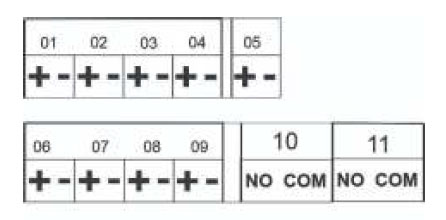
01 : LOW AIR
02 : DV OPEN
03 : MAIN FAP
04 : MANUAL CALL POINT
05 : SOLIENOID
06 : LOW AIR HOOTER
07 : DV OPEN HOOTER
08 : MAIN FAP HOOTER
09 : MANUAL PUSH BUTTON HOOTER
10 : COMMON ALARM
11 : COMMON FAULT
Downloads
Our Clients